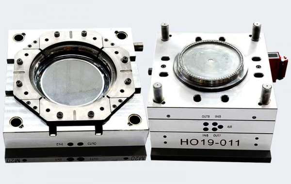
The usual underfeed Plastic Pail Mould is made up of 3 basic components, namely: the moving half, the floating impressions plate and the feed plate correspondingly.
The moving section has the shifting injection mold plate installation, support blocks, backing plate, ejector installation and the pin’s ejection strategy. Thus the moving half in this design is identical with the moving half of basic tools.
The drifting impressions plate, which could be of the integer or insert-bolster design, is positioned on substantial guide pins (not indicated) suited in the feed plate. These guide pins must be of ample duration to support the floating cavity plate in excess of its thorough activity and even so project to carry out the performance of alignment between the impressions and core while the mould tool is being closed. Guide bushes are installed in to the moving tool plate and the floating impressions plate respectively.
The most activity with the floating impressions plate is controlled by stop mounting bolts or similar devices. The moving tool bloster is suitably bored to present a clearance for the stop bolt assemblage. The stop bolts need to be long sufficient to offer ample space between the feed plate and the drifting impressions plate for uncomplicated removal of the feed strategy. The lowest space furnished for must be 66mm just suitable for an worker to take out the feed system by hand in case crucial.
The needed operating sequence is for the primary daylight to occur among the floating impressions plate and the feed plate. This ensures the sprue is pulled from the sprue bush quickly while the tool is opened. To reach this sequence, springs can be incorporated among the feed plate and the floating impressions plate. The springs needs to be strong enough to offer an extra initial impetus to the drifting cavity plate, to be sure it moves away using the moving half. It is common procedure to locate the springs on the guide pillars and accommodate them in appropriate pockets in the drifting cavity plate.
The serious aspect from the feed technique (runner and sprue) is accomm automatic operating, the runner needs to be of a trapezoidal shape so one plate is can simply be extracted. Observe that ,if a round runner is make by using floating cavity plate, where it would retain, and be stopped from when the tool is opened.
Because we have viewed the tool installation in many detai for this kind of tool.machine platens begin to open. A force is rapidly exerted by the compression springs, which causes the floating cavity plate to move away with the moving half as previously reviewed. The sprue is pulled from the sprue bush from the sprue puller. After the drifting impressions plate has moved an established distance, it is arrested through the stop bolts. The moving half is constantly move backside and the moldings, having shrunk on to the punches, are withdrawn out of the impressions.
The sprue puller, being attached to the moving half, is pulled through the floating impressions plate and thus releases the feed method which is consequently free to slip among the floating cavity plate and the feed plate?. The moving half continues to move rear until the ejector system is operated and the 18L Pail Moulds are ejected.Once the tool is shut, the respective plates are came back to their molding situation and the cycle is repeated.